
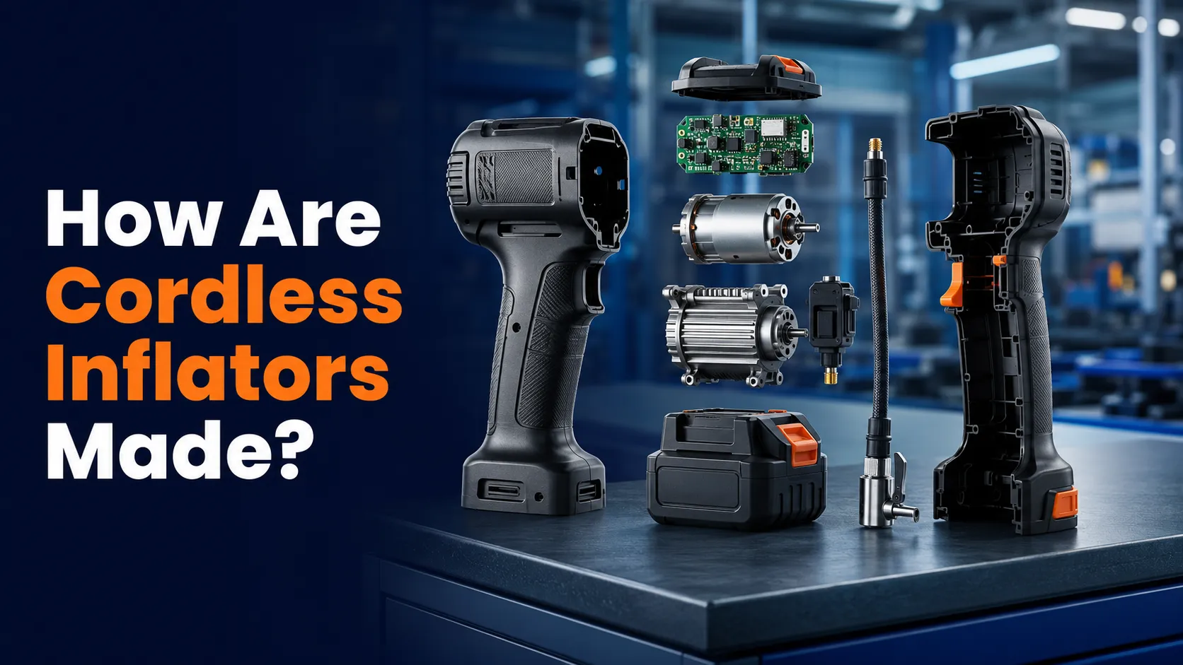
How are cordless inflators made? Most models begin as a collection of separate electrical, mechanical, and molded parts. A rechargeable battery powers a compact motor. The motor drives a small air-compressor mechanism, while a hose, valve connector, pressure sensor, control board, and plastic housing turn those parts into a portable tool.
The exact design and factory process vary by brand and model. Still, understanding the main stages helps you judge build quality, use the inflator correctly, and recognize why some repairs should be left to an authorized service center.
Cordless inflators are made by assembling a battery-powered motor, compact compressor, air path, pressure-control electronics, display, controls, and protective housing. Manufacturers produce or source the parts, assemble them into modules, connect and seal the air system, load the control software when needed, close the housing, and test the finished tool for operation, pressure response, leakage, heat, and basic safety.
What Parts Go Into a Cordless Inflator?
A cordless inflator looks simple from the outside, but several systems must work together. The exact parts depend on whether the tool is a small handheld pump, a power-tool battery model, or a dual-purpose inflator with separate high-pressure and high-volume modes.
| Part | Typical Material or Type | Main Job | Why Quality Matters |
|---|---|---|---|
| Outer housing | Molded engineering plastic | Holds and protects components | Controls fit, impact protection, and airflow |
| Electric motor | Brushed or brushless design | Creates rotary motion | Affects noise, heat, life, and efficiency |
| Compressor | Piston, cylinder, seals, and valves | Compresses outside air | Affects airflow, pressure, and leakage |
| Control electronics | Circuit board, switches, and wiring | Controls power and display functions | Supports stable and safe operation |
| Pressure sensor | Electronic sensing element | Measures pressure in the air path | Influences readings and auto-stop behavior |
| Hose and chuck | Reinforced flexible hose and metal or plastic fitting | Carries air to the valve | A secure seal reduces air loss |
| Battery system | Removable pack or built-in rechargeable cells | Supplies portable electrical power | Affects run time, protection, and charging safety |
How Is the Outer Housing Made?
The housing is commonly formed as two or more plastic sections. In a typical high-volume process, plastic pellets are heated and injected into a metal mold. After the material cools, the molded piece is removed and trimmed if needed.
The mold can form screw posts, vents, battery rails, switch openings, hose storage, ribs, and mounting points in one part. Internal ribs help position components and can make the shell stiffer without turning it into a solid, heavy block.
Engineers must also plan ventilation. The motor and compressor create heat, so vents need a clear path for cooling air. Poor component placement or blocked vents can allow heat to build up even when the outside shape looks attractive.
How Is the Compressor Mechanism Built?
Many compact high-pressure inflators use a small piston-and-cylinder arrangement. The motor spins, and a gear or offset drive changes that rotation into back-and-forth piston movement. As the piston moves, the compressor draws in outside air and then pushes compressed air toward the outlet.
Small valves control the direction of airflow. Seals help limit leakage around the moving piston and at joints. The cylinder, piston, drive parts, valve plate, and seals must fit closely enough to build useful pressure without creating excessive friction.
Materials vary. A manufacturer may use metals where heat, wear, or stiffness matters and engineered plastics or elastomers where lower weight, sealing, or vibration control is useful. The selection depends on the intended pressure range, duty cycle, tool size, cost, and service life.
Why does the motor need gears or an offset drive?
An electric motor naturally produces spinning motion, while a piston must move in a straight repeating stroke. A gear train, crank, eccentric bearing, or similar motion-conversion part connects those two actions. This area carries repeated loads and must remain aligned during operation.
How Are the Electronics and Pressure Controls Added?
A basic model may use a switch, motor, wiring, and an analog gauge. A digital auto-stop model needs more electronics. Its circuit board can receive input from the buttons and pressure sensor, show information on a display, control the motor, and stop inflation when the selected pressure is reached.
The pressure sensor connects to the air path so it can detect pressure at the outlet or hose. The control system converts that sensor signal into the displayed unit. Designs with automatic shutoff compare the measured pressure with the target selected by the user. An official DEWALT inflator description, for example, identifies a digital gauge and auto-shutoff as features of its supported model; that does not mean every cordless inflator uses the same control design.
During electronic assembly, components are mounted to a printed circuit board and soldered in place. Wires, battery contacts, display parts, switches, lights, and the motor are then connected. Insulation, routing clips, and connectors help keep wiring away from moving or unusually hot parts.
How Is the Battery System Integrated?
Some inflators accept a removable power-tool battery. In this layout, the inflator housing includes matching rails, contacts, and electrical communication features for the approved battery system. Other compact models contain rechargeable cells inside the tool and use a charging port.
A battery pack is more than a group of cells. Depending on its design, it can include cell connections, temperature sensing, current protection, electronic monitoring, terminals, insulation, and a protective case. The tool may also include its own protection and control circuits.
Battery and charger compatibility is set by the manufacturer. Similar voltage labels or a physically similar shape do not prove that two packs are interchangeable. The U.S. Consumer Product Safety Commission’s battery information identifies overheating, fire, charger shock, and burns among potential battery hazards, which is why the approved charging equipment and product instructions matter.
How Are Cordless Inflators Assembled?
The exact factory sequence is proprietary and varies by product, but a common assembly flow can be understood as a series of modules. Some manufacturers build many parts themselves, while others receive motors, cells, circuit boards, hoses, or molded components from specialist suppliers.
-
Inspect incoming parts
Workers or automated systems check selected dimensions, appearance, electrical properties, and supplier documentation before parts enter production.
-
Build the motor and compressor module
The drive components, piston or other pump mechanism, valves, seals, and outlet path are aligned and secured.
-
Prepare the control module
The circuit board, display, buttons, sensor, switches, and wiring are assembled and checked.
-
Install the modules in the housing
Internal mounts hold the compressor, motor, controls, battery interface, light, and other fitted parts in their intended positions.
-
Connect the air path
The pressure outlet, sensor connection, hose, seals, and chuck are fitted so compressed air can reach the tire valve with limited leakage.
-
Route and secure electrical connections
Wires and connectors are placed away from pinch points, moving components, and hot surfaces.
-
Close and fasten the housing
The housing sections are aligned and secured with screws, clips, or another specified fastening method.
-
Test and pack the finished tool
The unit receives the required checks before labels, instructions, accessories, and packaging are added.
How Are Finished Inflators Tested?
Manufacturers set their own quality plans, so not every factory performs the same tests on every unit. Production checks can occur at incoming inspection, during module assembly, at the end of the line, or through sample testing from a batch.
- Confirm that the motor starts, runs, and stops through the intended controls.
- Check that the air system builds pressure and does not show unacceptable leakage.
- Compare sensor and display behavior with the maker’s reference equipment.
- Verify auto-stop operation on models designed with that feature.
- Check switches, display segments, lights, charging functions, or battery contacts as applicable.
- Observe current draw, unusual vibration, noise, or heat against production limits.
- Inspect the hose, chuck, fasteners, labels, housing fit, and included accessories.
- Perform any required electrical, battery, durability, drop, packaging, or compliance checks under the manufacturer’s quality plan.
A passed factory test does not remove the need for correct use. A portable inflator still has an operating limit, cooling requirement, approved power source, and intended pressure range described in its instructions.
Why Are Some Cordless Inflators Built Differently?
Manufacturers balance pressure, airflow, size, weight, noise, heat, battery use, durability, features, and cost. A compact pump built mainly for bicycle or passenger-car tires may use a different motor and compressor layout from a larger tool intended for higher air volume.
- Secure internal mounts can control movement and vibration.
- Clear ventilation can support heat management.
- Strain relief can protect the hose and wiring at entry points.
- Replaceable batteries can extend usable time when approved spares are available.
- More compact construction can leave less room for cooling.
- Higher airflow or pressure can require a larger drive system.
- Extra displays, lights, and ports add parts and connections.
- A sealed design may be harder for an owner to service safely.
Maximum pressure alone does not describe inflation speed, duty cycle, gauge behavior, or suitability for a particular tire. Check the product manual and vehicle requirements instead of assuming that one headline specification explains the whole design.
What Can You Check Without Taking an Inflator Apart?
You cannot confirm every internal material from the outside, and opening the tool can expose electrical parts, damage seals, or affect warranty coverage. A careful external inspection is safer and still useful.
- Read the model label, instructions, operating limit, and approved battery information.
- Check that the housing sections meet evenly and the fasteners are secure.
- Inspect the hose for cracks, kinks, loose fittings, and poor strain relief.
- Confirm that the chuck attaches securely without forcing the tire valve.
- Make sure the controls are clear and the display is readable.
- Keep vents unobstructed and look for signs of melting or heat damage.
- Verify the final tire pressure with a dependable gauge if the reading seems doubtful.
Does the Manufacturing Method Affect Safe Use?
Construction quality can influence sealing, wiring protection, heat control, pressure measurement, and mechanical durability. Safe use also depends on the owner following the intended operating and cooling limits.
Stop using the inflator if it produces smoke, sparks, melting, a burning odor, extreme heat, exposed wiring, or repeated unexplained shutdowns. Do not bypass a thermal cutoff, fuse, pressure control, battery protection system, or automatic shutoff. Contact the manufacturer or a qualified service provider when the cause is unclear.
An inflator can add air, but it cannot repair a puncture, damaged sidewall, leaking rim, or faulty tire valve. Do not use continued inflation to hide a tire that cannot hold pressure.
Frequently Asked Questions
What is inside a cordless tire inflator?
A typical cordless tire inflator contains a battery connection or built-in battery, electric motor, compact compressor, air valves, hose, tire chuck, pressure sensor or gauge, controls, wiring, and a protective housing. Features and internal layouts vary by model.
What type of compressor is used in a cordless inflator?
Many compact high-pressure models use a small piston moving inside a cylinder, with valves controlling airflow. Other designs may use a different pump mechanism, especially when the tool includes a separate high-volume mode.
How is a cordless inflator housing made?
The housing is commonly made from molded plastic sections. The molding process can form vents, screw posts, battery rails, ribs, control openings, and storage areas before the sections are assembled around the internal parts.
How does an inflator measure tire pressure?
A digital model commonly uses an electronic sensor connected to the pressurized air path. Its control board converts the sensor signal into a displayed reading and may use it for automatic shutoff when that feature is included.
Are cordless inflators tested at the factory?
Manufacturers normally use production and quality checks, but the exact plan varies. Checks may cover motor operation, pressure response, air leakage, controls, display functions, battery connections, heat, noise, housing fit, labels, and included parts.
Are cordless inflator batteries made into the tool?
Some compact inflators have built-in rechargeable cells, while others accept a removable battery pack from an approved tool system. The battery, charger, contacts, and protection design must match the manufacturer’s requirements.
Can I open a cordless inflator to inspect how it is made?
Opening the housing can expose moving or electrical parts, disturb seals, create a pinched wire, or affect warranty coverage. Use external checks and manufacturer-approved service unless you have the proper technical information and qualifications.
Does a metal cylinder mean an inflator is better?
Not by itself. Material choice is only one part of the design. Alignment, seals, valves, motor loading, heat control, wiring protection, quality checks, and correct use also affect how the complete inflator performs.
Related Guides
- How Do Cordless Inflators Inflate Tires?
- How Long Do Cordless Inflator Batteries Last?
- Are Cordless Inflators Safe to Use?
- Why Does a Tire Inflator Get Hot?
- How to Maintain a Cordless Tire Inflator
Conclusion: How Are Cordless Inflators Made?
Cordless inflators are made by combining a rechargeable power system with a motor, compact compressor, sealed air path, pressure controls, hose, and molded housing. The factory assembles these parts into modules, connects the mechanical and electrical systems, closes the housing, and applies its required production checks.
Design details vary, so judge an inflator by its complete instructions, intended use, duty cycle, battery compatibility, external construction, and manufacturer support rather than one advertised number. Inspect the tool without opening it, keep the cooling vents clear, and stop using it if the battery, wiring, hose, or housing shows unsafe damage.
A cordless inflator is a coordinated system, not just a motor in a plastic case. Its battery, compressor, seals, sensor, controls, hose, ventilation, and assembly quality all matter. Follow the exact model instructions and use manufacturer-approved service instead of opening or bypassing safety features.